


In the field of electronics, NPN transistors are widely used due to their excellent amplification and switching capabilities. However, one common issue that engineers and enthusiasts often encounter is the presence of noise in NPN transistors. Noise can degrade the performance of electronic circuits, leading to inaccurate signal processing and reduced overall system reliability. As a reputable NPN transistor supplier, we understand the importance of addressing this issue and are committed to providing effective solutions. In this blog post, we will explore various methods to reduce the noise of an NPN transistor.
Understanding Transistor Noise
Before delving into the noise reduction techniques, it is essential to understand the sources of noise in NPN transistors. There are primarily three types of noise: thermal noise, shot noise, and flicker noise.
-
Thermal Noise: Also known as Johnson - Nyquist noise, thermal noise is generated due to the random motion of charge carriers (electrons) in the transistor's resistive elements. It is proportional to the temperature and the resistance of the material. The formula for thermal noise voltage is (V_{n}=\sqrt{4kTR\Delta f}), where (k) is the Boltzmann's constant ((1.38\times 10^{- 23}\ J/K)), (T) is the absolute temperature in Kelvin, (R) is the resistance, and (\Delta f) is the bandwidth of the measurement.
-
Shot Noise: Shot noise occurs due to the discrete nature of the current flow in the transistor. When electrons cross a potential barrier, such as the base - emitter junction, the flow is not continuous but rather a series of discrete events. This results in fluctuations in the current, which manifest as shot noise. The shot noise current is given by (I_{n}=\sqrt{2qI\Delta f}), where (q) is the elementary charge ((1.6\times10^{-19}\ C)) and (I) is the average current.
-
Flicker Noise: Flicker noise, also called 1/f noise, is more prominent at low frequencies. Its origin is not fully understood, but it is believed to be related to surface effects and the trapping and detrapping of charge carriers at the semiconductor - insulator interfaces. The power spectral density of flicker noise is inversely proportional to the frequency ((1/f)).
Selection of Low - Noise Transistors
One of the most straightforward ways to reduce noise is to select NPN transistors with low - noise characteristics. When choosing a transistor, pay attention to the noise figure (NF), which is a measure of how much the transistor degrades the signal - to - noise ratio (SNR) of an input signal. A lower noise figure indicates better noise performance.
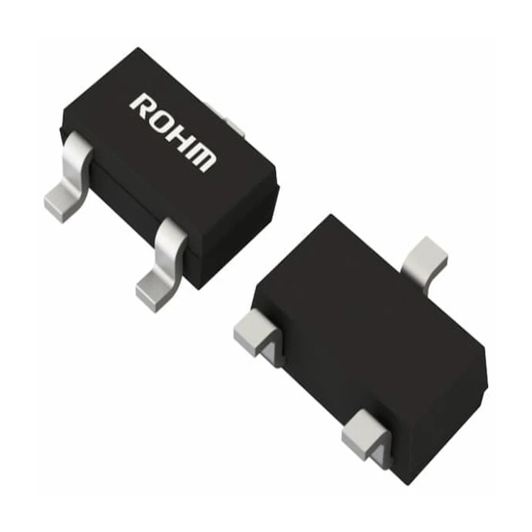
We offer a wide range of NPN transistors, including High - speed Switching NPN Transistor and Low Power Consumption NPN Transistor. These transistors are carefully designed and manufactured to minimize noise while maintaining high performance in terms of speed and power consumption.
Biasing Optimization
Proper biasing of the NPN transistor is crucial for noise reduction. The bias point determines the operating conditions of the transistor, such as the collector current ((I_{C})) and the base - emitter voltage ((V_{BE})).
-
Optimal Collector Current: The noise performance of a transistor is highly dependent on the collector current. In general, there is an optimal value of (I_{C}) at which the noise figure is minimized. For many transistors, the optimal (I_{C}) is in the range of a few milliamperes. By adjusting the biasing resistors in the circuit, the collector current can be set to this optimal value.
-
Stable Biasing Circuit: A stable biasing circuit is essential to maintain the desired operating point. Temperature variations can cause changes in the transistor's parameters, such as (V_{BE}) and (\beta) (current gain). Using techniques like voltage - divider biasing or emitter - bias stabilization can help to keep the operating point stable, reducing the impact of temperature - induced noise.
Circuit Layout and Grounding
The physical layout of the circuit can have a significant impact on the noise level.
-
Component Placement: Keep the components as close as possible to minimize the length of the interconnecting wires. Long wires act as antennas, picking up electromagnetic interference (EMI) from the environment. Place the transistor and its associated passive components in a compact and organized manner to reduce the chances of coupling between different parts of the circuit.
-
Grounding: A proper grounding scheme is crucial for noise reduction. Use a single - point ground or a star - shaped grounding system to avoid ground loops. Ground loops can cause unwanted current flow, leading to additional noise in the circuit. Connect all the ground points of the circuit to a common ground plane to provide a low - impedance path for the return current.
Filtering
Filtering is an effective way to reduce noise in the circuit.

-
Low - Pass Filters: Since flicker noise is more prominent at low frequencies, a low - pass filter can be used to attenuate the low - frequency noise components. A simple RC low - pass filter can be added at the input or output of the transistor circuit. The cut - off frequency of the filter should be chosen based on the frequency range of the signal of interest and the frequency range where the noise is most significant.
-
Power Supply Filtering: The power supply can be a source of noise. Adding capacitors across the power supply terminals can help to filter out the high - frequency noise components. Electrolytic capacitors are typically used for low - frequency filtering, while ceramic capacitors are used for high - frequency filtering.
Shielding
In some cases, especially when dealing with high - sensitivity circuits, shielding can be used to protect the transistor from external electromagnetic interference.
-
Faraday Cage: A Faraday cage is an enclosure made of a conductive material, such as metal. It can block external electromagnetic fields from reaching the transistor circuit. Place the transistor and its associated components inside a Faraday cage to reduce the impact of EMI.
-
Shielded Cables: If the circuit is connected to external devices using cables, use shielded cables to prevent the cables from acting as antennas and picking up EMI. The shield of the cable should be properly grounded to provide an effective shielding effect.
Feedback Techniques
Negative feedback can be used to reduce the noise in the transistor circuit.
-
Voltage Feedback: By applying voltage feedback, the gain of the transistor circuit can be stabilized, and the noise can be reduced. A fraction of the output voltage is fed back to the input in such a way that it opposes the input signal. This reduces the overall gain of the circuit but improves the linearity and reduces the noise.
-
Current Feedback: Current feedback is another technique that can be used to reduce noise. In a current - feedback amplifier, the feedback signal is proportional to the output current. This type of feedback can provide better high - frequency performance and noise reduction compared to voltage feedback.
As an NPN transistor supplier, we are dedicated to helping our customers solve the noise problems in their circuits. Our team of experts is always ready to provide technical support and advice on choosing the right transistors and implementing effective noise reduction techniques. If you are interested in purchasing our NPN transistors or need further assistance with noise reduction in your circuits, please feel free to contact us for a procurement negotiation. We look forward to working with you to achieve high - performance and low - noise electronic systems.
References
- Boylestad, R. L., & Nashelsky, L. (2012). Electronic Devices and Circuit Theory. Pearson.
- Sedra, A. S., & Smith, K. C. (2015). Microelectronic Circuits. Oxford University Press.
- Horowitz, P., & Hill, W. (2015). The Art of Electronics. Cambridge University Press.


