


Hey there! As a supplier of power management ICs, I've seen my fair share of electromagnetic interference (EMI) problems that can really mess up the performance of these chips. In this blog, I'm gonna share some tips on how to solve those pesky EMI issues.
Understanding EMI in Power Management ICs
First off, what exactly is EMI? Well, EMI is basically the unwanted noise or interference caused by electromagnetic fields. These fields can be generated by a whole bunch of things, like other electronic devices, power lines, or even the power management IC itself. When EMI occurs, it can lead to all sorts of problems, such as signal distortion, reduced efficiency, and even complete failure of the device.
In power management ICs, EMI can be a real headache because these chips are responsible for regulating and controlling the power supply to various components in a system. Any interference can disrupt the normal operation of these components, leading to performance issues.
Common Sources of EMI in Power Management ICs
There are several common sources of EMI in power management ICs. One of the main culprits is switching noise. Power management ICs often use switching regulators to convert and control the power supply. These regulators switch on and off at high frequencies to regulate the output voltage. However, this switching action can generate high - frequency noise, which is a major source of EMI.
Another source of EMI is the layout of the printed circuit board (PCB). If the PCB layout is not designed properly, it can create loops and traces that act as antennas, radiating electromagnetic energy and causing interference.
The power input and output lines can also be a source of EMI. These lines can pick up noise from other parts of the system or from external sources. And if the power lines are not properly filtered, this noise can be transmitted to the power management IC and cause problems.
Solving EMI Problems
1. Component Selection
One of the first steps in solving EMI problems is to choose the right components. For example, when selecting a power management IC, look for chips that have built - in EMI reduction features. Some ICs come with spread - spectrum clocking, which spreads the energy of the switching frequency over a wider bandwidth, reducing the peak EMI.
Also, pay attention to the quality of passive components like capacitors and inductors. High - quality components with low equivalent series resistance (ESR) and equivalent series inductance (ESL) can help reduce EMI. For example, using ceramic capacitors with low ESR can effectively filter out high - frequency noise.
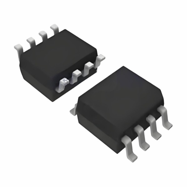
Our company offers a wide range of power management ICs, including Load Switch Control IC, Lithium Battery Protection IC, and Power Path Management IC. These ICs are designed with advanced EMI reduction techniques to ensure reliable performance.
2. PCB Layout Optimization
The PCB layout plays a crucial role in reducing EMI. Here are some key layout tips:
- Keep Traces Short: Short traces reduce the loop area and minimize the amount of electromagnetic energy radiated. This is especially important for high - current and high - frequency traces.
- Separate Power and Signal Traces: Power traces can carry a lot of noise, so it's important to keep them away from signal traces. Use ground planes to isolate power and signal layers.
- Use Proper Grounding: A good grounding scheme is essential for reducing EMI. Make sure there is a solid ground plane and that all components are properly grounded. Avoid ground loops, which can act as antennas and radiate EMI.
3. Filtering
Filtering is an effective way to reduce EMI. You can use passive filters, such as LC filters or RC filters, to block or attenuate high - frequency noise. Place these filters at the power input and output of the power management IC to prevent noise from entering or leaving the chip.
For example, an LC filter consists of an inductor and a capacitor. The inductor blocks high - frequency current, while the capacitor shunts high - frequency noise to ground. By choosing the right values for the inductor and capacitor, you can design a filter that is effective at the frequencies where the EMI is most prevalent.
4. Shielding
In some cases, shielding can be used to reduce EMI. Shielding involves enclosing the power management IC or the entire system in a conductive enclosure. The enclosure acts as a Faraday cage, blocking the electromagnetic fields from entering or leaving the system.
However, shielding can be expensive and may add some bulk to the system. So, it's usually used as a last resort when other methods of EMI reduction are not sufficient.

Testing and Verification
Once you've implemented the above solutions, it's important to test and verify the results. You can use various test equipment, such as spectrum analyzers and oscilloscopes, to measure the EMI levels. Make sure the EMI levels are within the acceptable limits specified by the relevant standards.
If the EMI levels are still too high, go back and re - evaluate your solutions. Maybe you need to adjust the component values, optimize the PCB layout further, or add more filtering.
Conclusion
Solving EMI problems in power management ICs is a challenging but important task. By understanding the sources of EMI, carefully selecting components, optimizing the PCB layout, using proper filtering, and testing and verifying the results, you can effectively reduce EMI and ensure the reliable performance of your power management ICs.
If you're facing EMI issues with your power management ICs or are looking for high - quality power management solutions, we'd love to hear from you. Our team of experts can help you find the right products and provide customized solutions to meet your specific needs. Don't hesitate to reach out for a procurement discussion and let's work together to solve your power management challenges.
References
- "Electromagnetic Compatibility Engineering" by Henry W. Ott
- "Power Electronics: Converters, Applications, and Design" by Ned Mohan, Tore M. Undeland, and William P. Robbins
- Manufacturer datasheets of power management ICs


